In high-volume electronics manufacturing, reflow soldering precision directly impacts product reliability.
With lead-free mandates (e.g., RoHS) requiring peak temperatures up to 260°C and components shrinking to 01005 size (approximately 0.4mm × 0.2mm), process control is critical.
This guide provides actionable techniques to address key challenges: thermal profiling for complex boards, void reduction below 5% for automotive applications, and IPC Class 3 compliance—all of which rely on the following technologies to meet the standard’s strict requirements for solder joint reliability.

• Yield Impact: Defects like tombstoning or cold joints can cost $50k/hour in downtime. Industry data shows that optimized profiles reduce rework by 40%.
• Compliance Demands: Lead-free solders (e.g., SAC305) require precise temperature control (±2°C) to prevent delamination.
• Miniaturization: 0.3mm pitch BGAs demand void rates <3%, achievable through advanced vacuum technology.
Stencil Design: Laser-cut apertures (0.1mm) with electroformed nickel ensure ±10% volume consistency.
SPI Integration: 3D solder paste inspection detects insufficient deposits before reflow, reducing defects by 30%.
High-speed placers achieve 0.03mm precision.
Calibration protocols using moiré phase-shift technology prevent misalignment.
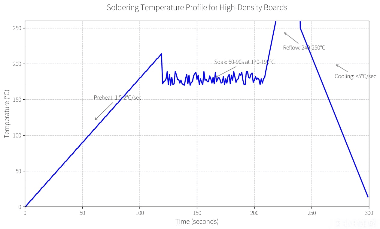
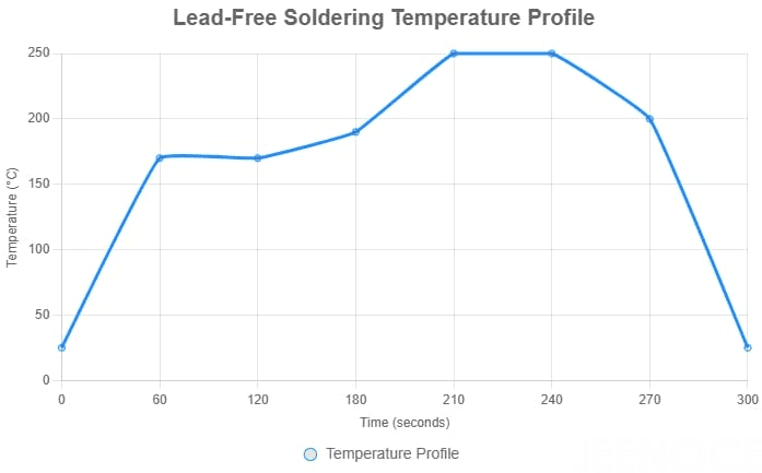
For general high-density boards: Preheat at 1.5-2°C/sec → Soak for 60-90s at 170-190°C → Reflow at a peak of 240-250°C → Cooling at <5°C/sec
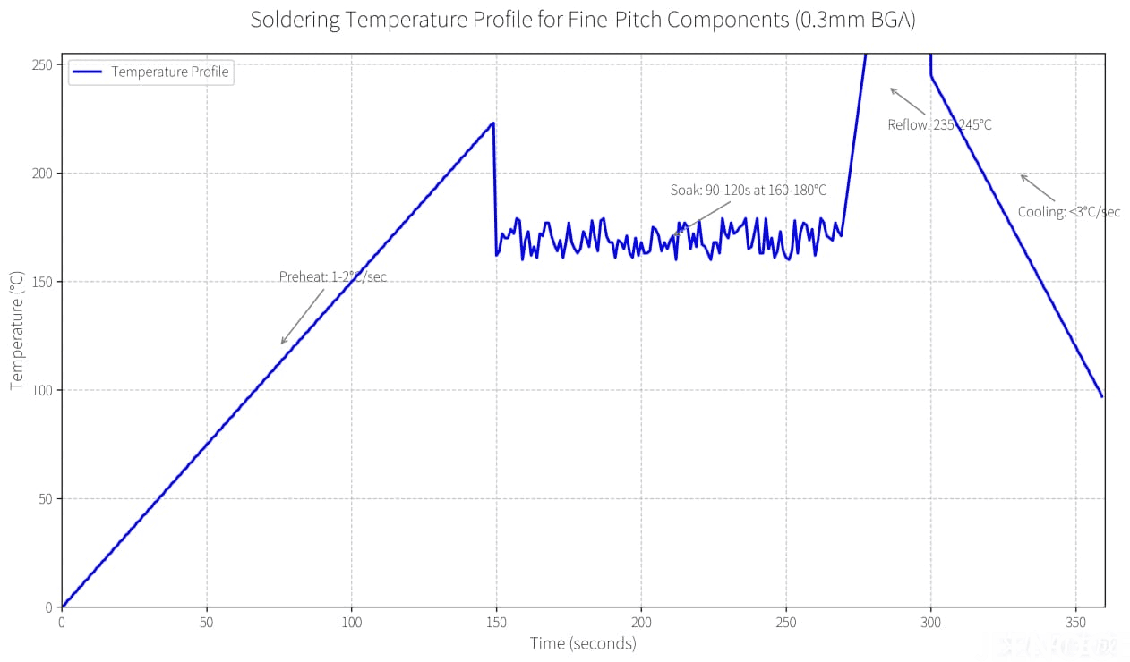
For fine-pitch components (e.g., 0.3mm pitch BGAs): Preheat at 1-2°C/sec → Soak for 90-120s at 160-180°C → Reflow at a peak of 235-245°C → Cooling at <3°C/sec
“So, let me tell you about a real-world problem we tackled recently. I’ve been an engineer here at JEENOCE for over fifteen years, and I’ve seen a lot of issues come and go, but this one was a classic.”
We got a call from a big automotive supplier—you’d know the name. They were pulling their hair out because these tiny little components on their high-density boards were standing straight up on one end during soldering. We call that "tombstoning" and it’s a real pain. It was killing their production yield and driving up their costs.
So, my team and I went on-site to take a look. The first thing we always do is just… watch. We looked at their printer, their pick-and-place machines, and finally, we dove deep into their reflow oven settings. And bingo—we found our culprit.
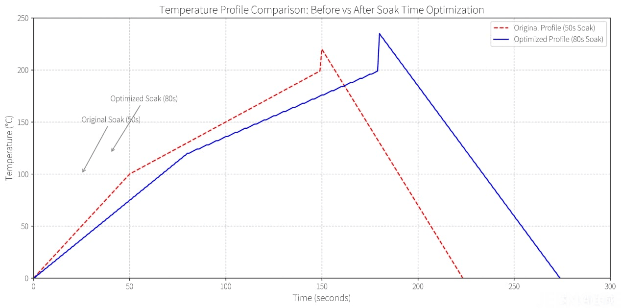
Their oven's "soak" time—that's the pre-heat stage before the real soldering heat hits—was way too short. It was only about 50 seconds. For these super dense, complicated boards they were making, that just wasn't cutting it. It wasn't giving the board enough time to heat up evenly, so one end of a tiny component would melt and get pulled upright before the other end even got ready. It was like a tiny, destructive game of tug-of-war on every board.
Our fix? It sounds almost too simple, but it’s all about the details. We told them, "Let's slow things down a bit." We extended that critical soak time from 50 seconds to a full 80 seconds. This gave the entire board time to reach a nice, even temperature, so everything starts melting at the same time. No more tug-of-war.
We also suggested a different type of solder paste that's a bit more active for these small parts and made a tiny tweak to their stencil design to make sure the right amount of paste was being laid down.
You guess what happened? The results were night and day. Almost immediately, those tombstoning defects just plummeted. We’re talking a 90% drop. Their line started humming, their yield shot up, and they stopped wasting so much time and money on rework.
It just goes to show, sometimes the biggest wins come from understanding the process inside and out and not being afraid to make a precise, calculated change.
That’s what we do at JEENOCE. We don’t just sell equipment; we provide solutions that really work. It’s why our motto is "Our solutions, Your profits!"—because we’ve seen it happen, time and time again.

High-yield SMT production lines require equipment that meets the technical specifications outlined in the table below, as these parameters directly address challenges like miniaturization and void reduction.
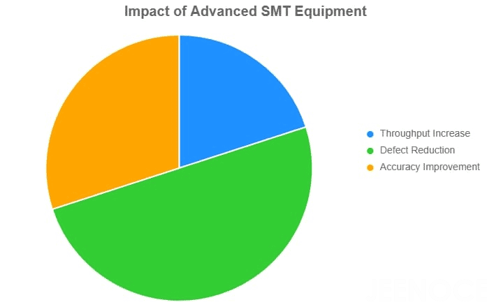
Equipment | Technical Specification | Impact |
Convection Ovens | 8-12 zones, ±1°C uniformity | 20% faster throughput vs. infrared ovens |
Vacuum Systems | <10 mbar pressure, 30s hold | Voids reduced from 15% to <2% |
AOI Systems | 5μm resolution, 0.1s/component | Escapes cut by 85% |
Pick and Place Machines | High-speed with 0.03mm precision | Enhanced accuracy for miniaturization, reducing misalignment by 50% |
As a leading provider of SMT lines integration and peripheral equipment, JEENOCE offers turn-key solutions that incorporate advanced convection ovens (with 8-12 zones for ±1°C uniformity) and vacuum systems (operating at <10 mbar pressure), aligning with its core advantages in digital factory systems and professional technical teams for seamless automation in electronics manufacturing.
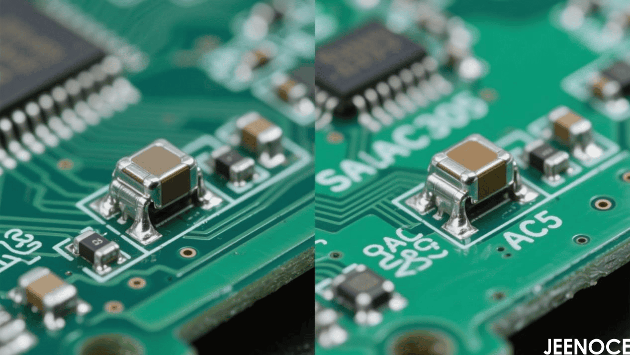
Lead-Free Solder Options Lead-free solders like SAC305 are essential for compliance, with melting points around 217°C. Select pastes with low-voiding flux to minimize defects in high-density boards.
JEENOCE's integration services ensure compatibility with customized non-standard automation systems for optimal material handling in electronics manufacturing processes.
Stencil Thickness: 100μm for 0.4mm CSPs vs. 130μm for QFNs. Anti-slump coatings prevent bridging. Using stencils involves automated printers for precise deposition, ensuring appropriate thickness to avoid insufficient solder deposits.
Nozzle Selection: 0402 components require nozzles with <5μm runout error. Utilizing pick and place machines ensures best practices for accurate placement, such as vision alignment systems for real-time correction.
• Vacuum Integration: Apply 5 mbar vacuum at liquidus to evacuate gases (critical for QFNs).
• Nitrogen Usage: Maintain O2 levels <500 ppm to improve wetting by 25%.
• Oven Type Selection: Convection ovens are ideal for uniform heating (suited for general boards), while infrared ovens work for targeted heating (for components with uneven heat demands).
• Temperature Profiles (consistent with Section 3): For general high-density boards, ramp to soak at 1.5-2°C/sec, soak at 170-190°C for 60-90s, reflow at a peak of 240-250°C for 15-60s, and cool at <5°C/sec
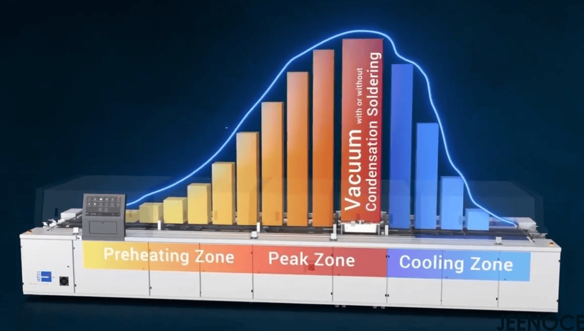
To learn more about temperature curve control, please move on to watch: How Temperature Zones Make or BreakSoldering Quality
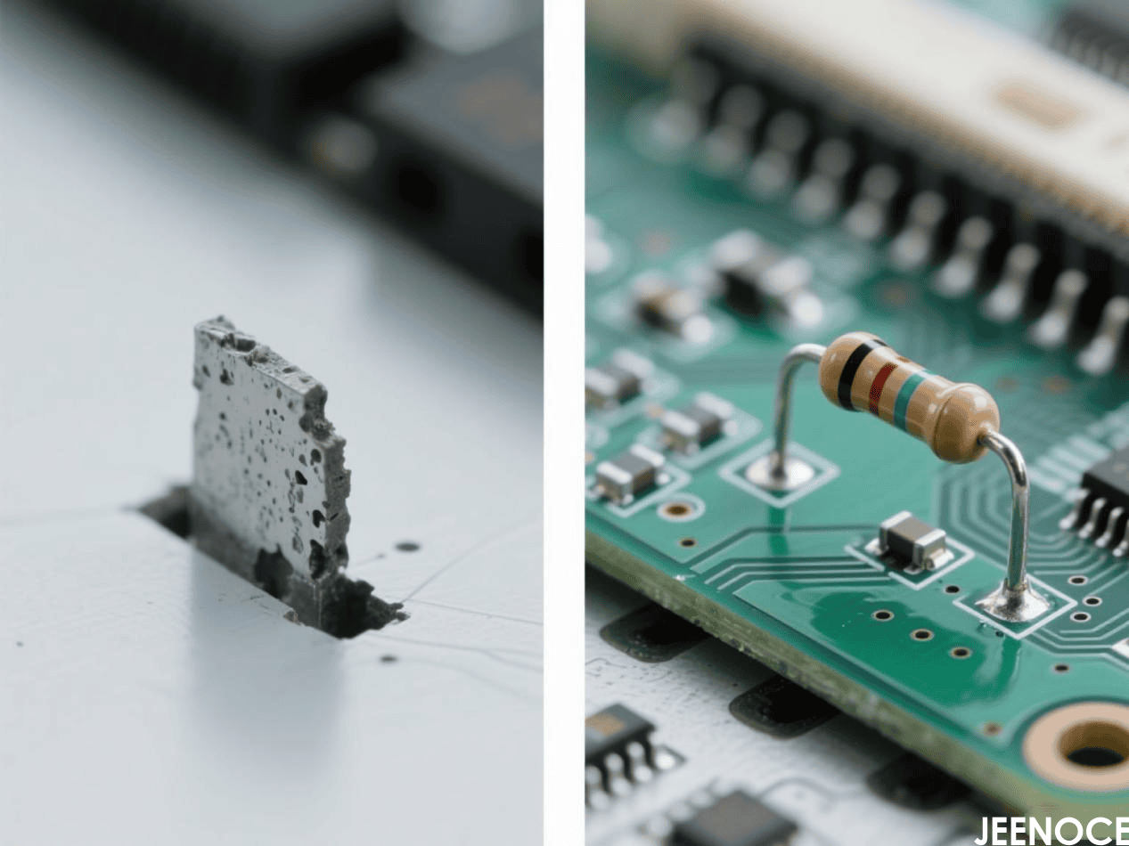
Cause: Uneven pad heating (ΔT >4°C across component).
Fix: Dual-lane thermal balancing + slower cooling (<3°C/sec). Common in short components like resistors, mitigated by balanced pad designs and finer pitch pastes.
A core strategy to address solder voids is optimizing flux formulations and preheat processes to prevent outgassing—supported by real-world data.
For example, a medical device OEM reduced BGA voids from 12% to 1.8% using vacuum-assisted reflow at 8 mbar, which complements the flux and preheat optimization (key for handling this specific SMT soldering defect).
• As the SMT Program Manager at Jeenoce, I am pleased to share a significant technical achievement:
Through our customized 8mbar vacuum-assisted reflow soldering process, we successfully reduced BGA solder voids from an industry-average 12% to just 1.8% for a medical device OEM client, markedly enhancing product reliability.
During project execution, our technical team prioritized defect prevention at the source by precisely optimizing flux activation parameters and multi-stage preheating profiles, effectively mitigating outgassing issues during high-temperature soldering.
Root Cause: Oxygen intrusion >1000 ppm or peak temperature deviation >5°C. Solutions for insufficient solder joint quality include nitrogen atmospheres and precise profile adjustments.
Do you want to reach a yield rate of 99%? Please move on to learn more:A Simple Guide to lmprove Joint Yield to 99.9%
5μm systems detect micro-bridges in 0.3mm pitch BGAs. Inspection techniques encompass visual inspection methods for initial checks and AOI for high-throughput verification.
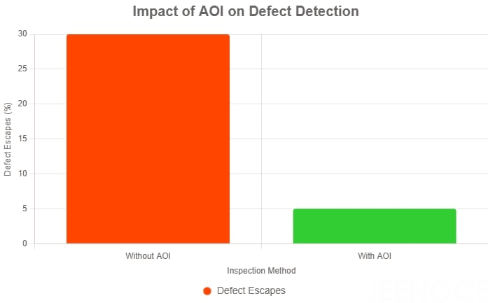
Real-time CpK >1.33 for critical parameters (e.g., peak temp, cooling rate).
AI predicts defects using thermal profile data, reducing false fails by 50%. JEENOCE's digital inline upgrade and test integration fixtures enhance quality assurance through MES and QS systems for traceable, high-reliability outputs.
Future trends in SMT soldering include vapor phase soldering for uniform heating, inline AI optimization for predictive maintenance, and digital twins for simulation—technologies JEENOCE pioneers in their core business of SMT integration and automation, serving global clients in the automotive and medical sectors to enhance electronics manufacturing efficiency.
Message