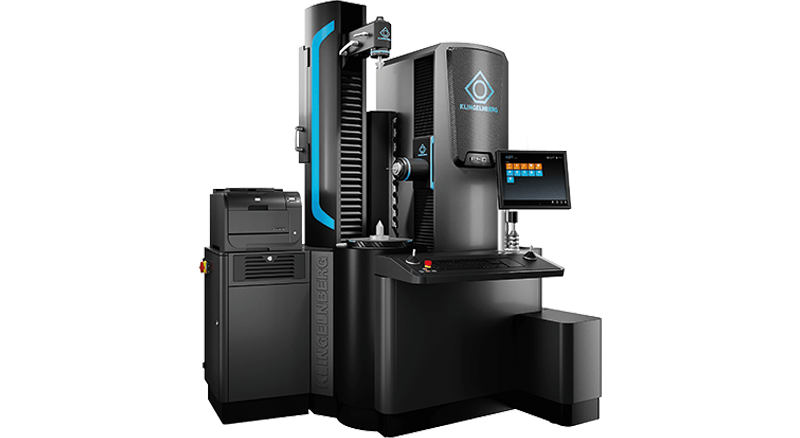
The fully automatic Gear Inspection Equipment is designed as a compact unit for the workpiece diameter range up to 400 mm.
The machine is used to inspect cylindrical gears, pinion type cutters and shaving cutters, worms and worm wheels, hobs, bevel gears, general dimension, shape, and positional deviations of axially symmetrical workpieces, cam and camshaft measurement and rotor measurement.
Suitable for use on the production floor thanks to temperature compensation –reliable measuring results even in the + 15°C to + 35°C range.
Fast and accurate measurement acquisition, combined with a high-precision workpiece turntable.
A wide range of measurement tasks in a single clamping, suitable for coordinate, shape, gear tooth and roughness measurements.
Versatile scanning 3D tracer head with digital measurement acquisition in all coordinate directions
High basic accuracy with low tolerances.
Simple graphical programming environment and simple software operating concept.
Tremendous time savings due to quick availability of measuring results.
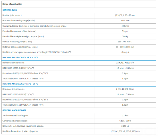
The machine dimensions of the standard version are for orientation only.
The final machine dimension / final space requirement depends on the individual configuration of the machine.
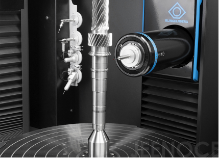
Extremely smooth-running rotary table axis in form-measurement quality
Load reserves for impacts during workpiece loading
Rotary table drive via AC torque motor (direct drive)
Uniform, constant rotary transmission even at extremely slow-motion
Directly coupled angle measuring system with high absolute accuracy
Table freely rotatable when drive is shut down
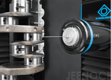
Coupled measuring movements of up to four axes simultaneously, also for form measurements
High-speed measuring even with high measuring point density
Intelligent control response of rotary table axis for different workpieces (moments of inertia/workpiece coupling)
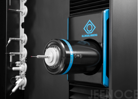
High-resolution scanning 3D tracer head with digital measured value logging in all coordinate directions
Parallel-deflecting system for constant data calculation even with extended probe elements
Automatic specification of trace direction in the X/Y plane when measuring lead lines with contact operation in the normal direction
Measured value logging in form measurement quality
Automatic compensation of different probe weights and adaptation of probe rods with multiple probe elements
Automatic measuring probe change (optional)
Scanning in axial, face, tangential and normal section
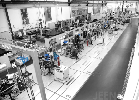
Long-term stable geometry of all machine-mounted accessories and guide systems thanks to large size and use of high-quality materials
Extremely smooth-running rotary tables even under load
Use of length measuring/angle measuring systems in the highest accuracy classes
Residual error calculation via special testing devices and controllerintegrated compensation
Modern assembly system with low error rates based on pretested modules
Constant measuring accuracies of all machine models
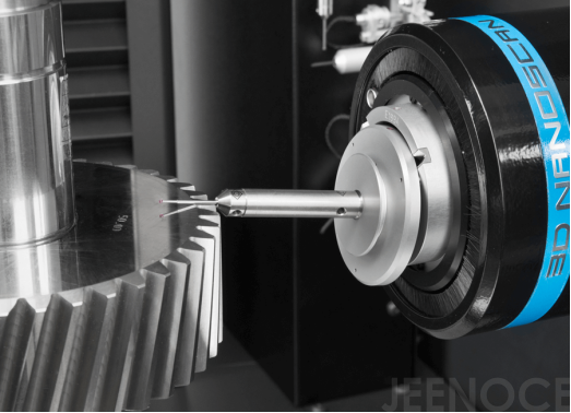
Software operator guidance with plausibility check of programming data
3D tracer head with deflection motion monitoring via sensors and a mechanical safety device
Probe change rack with bistable magnet holding system for easy handling and reliable collision protection
Monitored measuring axis drives with overload protection function
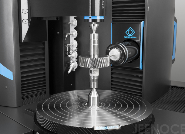
Testing of all measuring centers with masters for profile and tooth trace and workpiece-like masters of different types and sizes
Traceability of measuring results to internationally recognized masters
Proof of length measurement uncertainty MPEE (optional)
Proof of system suitability for form measurement tasks (option)
Determination of parameters Cg/Cgk and R&R testing (option)
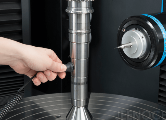
Correction of measuring results for workpiece temperatures deviating
from the reference temperature in the +15 to +35 °C range
Measurement of the current workpiece temperature via a fast thermoelement
Algorithm usable for all metallic/rotationally symmetric workpieces
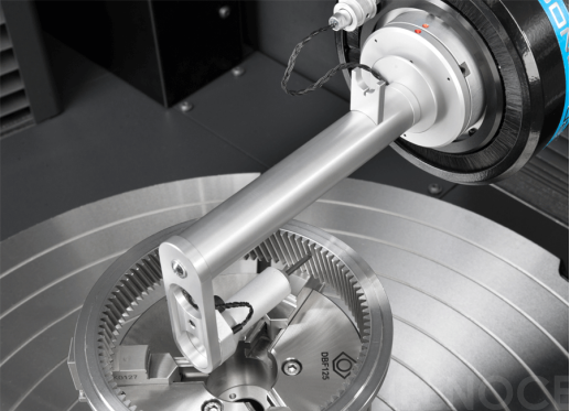
Skid-mounted tracer head for measured value logging on gearing with
modules starting at 0.9 mm
Output values acc. to DIN EN ISO 4287 (DIN 4762): Ra, Rz (DIN), Rt, Rmax, R3z,
Rq, Rpc, Rk, Rpk, Rvk, MR1. MR2. R, AR
Scanning in the profile or lead line direction with standardized trace sections
Fully automatic operation in connection with profile and lead measurements, as well as for shaft probing and on plane surfaces
Integrated actuator for diamond scanner alignment
Probing systems for dimension, form and position of cylindrical and bevel gear toothing Manual or (optional) fully automatic measuring probe change
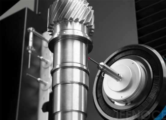
Determination of measurement parameters such as diameter, length, angle, radius
Determination of form and position parameters such as roundness, cylindrical shape, straightness, evenness, parallelism, symmetry, perpendicularity
Measurement and evaluation macros for checking feather- and woodruff- keyways and for checking bore reference circles
Measured value chart output for form measurements with filter levels standardized according to DIN EN ISO 1101
Linking of dimension/form/length measurements with gear measurements (cylindrical gear/bevel gear) for a continuous, fully automatic measuring run
Scanning in the axial / transverse section for measuring radii and clearance grooves, in the normal section for measuring tooth root radii and tip chamfers, as well as in the tangential section for measuring coupling elements
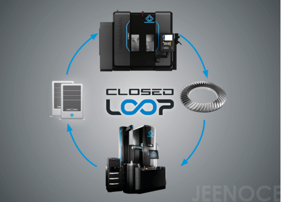
Bevel gear tooth trace measurement compared against nominal data to be calculated
Measurement of correction setting data for the machining method (cutting/grinding) based on current measured data
Network data transmission for all integrated production facilities
Ability to manufacture bevel gear sets (ring gear/pinion) as replaceable individual parts (grinding work)
Reverse Engineering of bevel gear sets
Tool measurement (stick blades) compared against calculated nominal data and reverse engineering with correction on the stick blade grinding machine
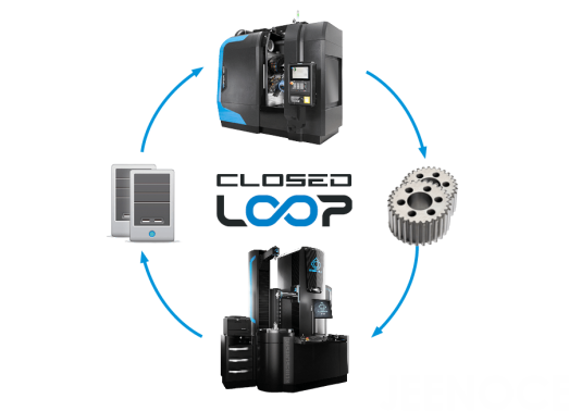
Safe corrections thanks to error-free data transmission
Elimination of error influencing variables through manual input
Optimal process control through continuous closed loop process Data transmission via one standard interface
Freely usable interface for cylindrical gear grinding machines
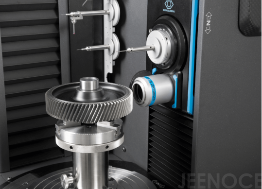
Fast measured value logging with high point density
Rapid changeover between tactile and optical probing systems
Very fast optical pitch measurement on cylindrical gears according to VDI/VDE 2613 Class 1 for reducing the pitch measurement time by up to 80%
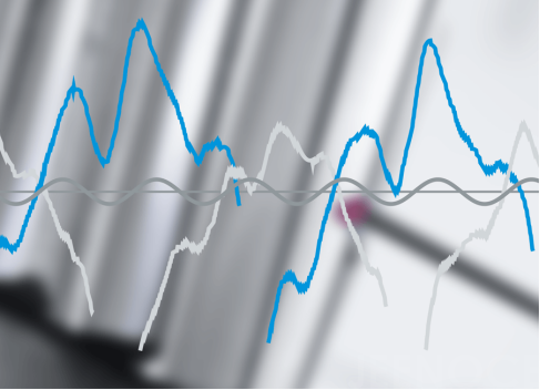
Measurement of the smallest wavelike deviations in form on gearing and their evaluation
Display of waviness and order spectra
Automatic waviness evaluation from a standard profile and lead measurement
Comparison with tolerance curves and OK/NOK evaluation
Transfer of parameters to a statistics program 10
Message
