Analysis of lead-free reflow soldering characteristics and countermeasures from temperature curves
Release time:2024-06-12Publisher:Jeenoce
Lead free reflow soldering is a type of reflow soldering. The early reflow soldering solder used materials containing lead. With the deepening of environmental protection thinking, people are paying more and more attention to lead-free technology (now known as lead-free reflow soldering). The greatest changes occur in materials, especially in solder. In terms of technology, the welding process has the greatest impact. JEENOCE shares here the characteristics and countermeasures of lead-free reflow soldering analyzed from the temperature curve.
1、 In the reflow soldering heating zone
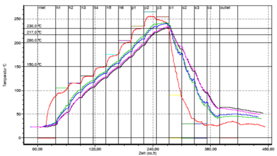
It only takes 60-90 seconds for lead welding to increase from 25 ℃ to 100 ℃ sec; However, lead-free soldering requires 100-200 seconds to rise from 25 ℃ to 110 ℃, and its heating time is twice that of lead. When multi-layer boards, large boards, and complex printed circuit boards with large thermal capacity components are used, in order to ensure uniform temperature distribution throughout the PCB and reduce the temperature difference Δ t between the PCB and large and small components, lead-free soldering requires slow heating. From this, it can be seen that lead-free welding requires the welding equipment to heat up and the length of the preheating zone to be extended.
2、 In the rapid heating zone of reflow soldering (flux infiltration zone)
Lead welding can be carried out from 150 ℃ to 183 ℃, with a temperature increase of 33 ℃, and can be completed within 30-60 seconds. The heating rate is 0.55-1 ℃/sec; However, lead-free welding is increased from 150 ℃ to 217 ℃, with a temperature rise of 67 ℃, and can only be completed between 50-70 seconds. The heating rate is 0.96-1.34 ℃/sec, which requires a heating rate about 30% higher than that of lead. The higher the temperature, the more difficult it is to raise the temperature. If the heating rate cannot be increased, prolonged exposure to high temperatures will cause the activation reaction of the flux in the solder paste to end prematurely. In severe cases, the PCB pads, component pins, and solder alloy in the solder paste will re oxidize at high temperatures, resulting in poor welding. In order to improve the heating slope of the flux infiltration zone, the number of reflow zones should be increased or the heating power should be increased. Due to high temperature and poor wettability, it is required to increase the activation temperature and activity of the flux in the solder paste.

3、 Looking at the reflow zone of reflow soldering again
The peak temperature with lead is 210-230 ℃, and the peak temperature without lead is 235-245 ℃. Due to the limit temperature of FR-4 substrate PCB being 240 ℃, it can be seen that when soldering with lead, a fluctuation range of 30 ℃ is allowed, and the process window is relatively loose; When lead-free welding is used, only a fluctuation range of 5 ℃ is allowed, and the process window is very narrow. If the surface temperature of the PCB is uniform, then the actual process allows for an error of 5 ℃. If there is a temperature error Δ t>5 ℃ on the surface of the PCB, then a certain part of the PCB has exceeded the limit temperature of FR-4 substrate PCB by 240 ℃, which will damage the PCB. This example is only suitable for simple products, for complex products with large heat capacity. It may take 260 ℃ to weld properly. Therefore, the FR-4 substrate PCB cannot meet the requirements.
In actual reflow soldering, on the same PCB, due to the different distribution areas of copper at different positions, the size and density of components at different positions are different, resulting in uneven surface temperature of the PCB. When reflow soldering, if the minimum peak temperature is 235 ℃, the maximum peak temperature depends on the temperature difference Δ t on the board surface, which depends on the size, thickness, number of layers, component layout, distribution of Cu, as well as component size and heat capacity. Large and thick printed boards with large and complex components (such as CBGA, CCGA, etc.) typically have Δ t values as high as 20-25 ℃. In order to reduce the Δ t on the surface of the PCB and meet the requirements of small lead-free process windows. The heat capacity and lateral temperature difference of the reflow soldering furnace are also important factors to ensure the quality of lead-free soldering. Generally, it is required that the transverse temperature difference of the reflow soldering furnace is less than 2 ℃. In order to reduce the transverse temperature difference Δ t of the furnace, in addition to taking better insulation measures for the furnace body, the method of heating the guide rail can also be used. Because the guide rail is easy to dissipate heat, the temperature arrow near the guide rail is generally slightly lower. Due to the fact that lead-free soldering equipment has a melting point 34 ℃ higher than those with lead, it is required that lead-free soldering equipment be resistant to high temperatures and corrosion. For large-sized PCBs, it is required to add intermediate support to the guide rails of the equipment.
4、 In the reflow soldering cooling zone
Due to the high peak temperature in the reflow zone, in order to prevent the growth of crystalline particles in the solder joints caused by long cooling and solidification time; In addition, accelerated cooling can prevent segregation and prevent the formation of dendritic crystals. Therefore, it is required to add cooling devices to welding equipment to quickly cool down the solder joints.

