Reasons for component misalignment and improvement after reflow soldering
Release time:2024-03-14Publisher:Jeenoce
The misalignment of components after reflow soldering is one of the two common defects in SMT. Below is a comprehensive analysis by JEENOCE on why SMT components may experience misalignment after reflow soldering, as well as the issue of misalignment. Some commonly used countermeasures are also provided for reference:
1、 Analysis and countermeasures of component misalignment after SMT reflow soldering
Reasons for component misalignment after reflow soldering:
1. The PCB board is too large and deforms when passing through the furnace;
2. The installation pressure is too low. The vibration of the reflow soldering chain is too high;
3. Collision board after production;
4. The NOZZLE problem (incorrect use of suction nozzle/blockage/inability to suction the center point of the part) causes uneven pressure on the placement part. Causing the component to slide on the solder paste
5. Poor soldering of components (unilateral soldering of components may cause pulling);
6. Machine coordinate offset.
Countermeasures for component misalignment after reflow soldering:
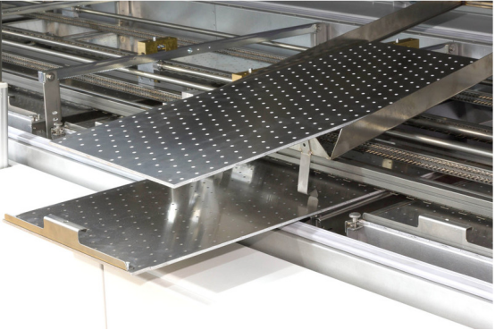
When the PCB board is too large, it can be passed through the furnace with a mesh belt;
2. Adjust the mounting pressure (taking SAMSUNG-SM321 as an example. The Z-axis pressure should be between -0.2 and -0.5. However, the value should not be too large. If it is too large, it will cause the machine NOZZLE to break/NOZZLE to block/NOZZLE to deform/machine Z-axis to bend);
3. Adjust the sensors between machines (the sensors should be close to the outside of the machine);
5. Replace materials;
6. Adjust the machine coordinates.

2、 Reasons and countermeasures for the occurrence of upright (standing monument) components after SMT reflow soldering
The reason for the component standing upright (monument) after reflow soldering:
1. The steel mesh holes are blocked;
2. The amount of tin added at both ends of the part is unbalanced;
3. OZZLE blockage (uneven suction caused by partial blockage of the Nozzle suction hole);
4. FEEDER offset (causing Nozzle to fail to suction, resulting in lateral suction);
5. Low machine accuracy;
6. The spacing between pads is too large/there are holes on the pads/the two ends of the pads are not of the same size;
7. Poor temperature setting (standing monument is a common welding defect in resistors and capacitors, caused by the uneven wetting force caused by the melting of solder paste on the component solder pads. The temperature gradient in the constant temperature zone is too large, which means that the temperature difference on the PCB board surface is too large. Especially, the temperature at both ends of the resistors/capacitors near the large components is not balanced due to heating, and there is a delay in the melting time of solder paste, which causes the defect of standing monument) Please check for details (how to correctly set the temperature curve for reflow soldering);
8. Components or pads are oxidized.
Countermeasures for upright components (monument):
1. Clean the steel mesh (require the operator to clean the steel mesh on time, and if necessary, use an air gun to blow during cleaning. It is strictly prohibited to wipe the steel mesh with paper, and use a dust cloth to wipe it);
2. Adjust the distance between the PCB and the steel mesh (the PCB must be parallel to the steel mesh);
3. Clean NOZZLE (clean NOZZLE on time according to the maintenance record of the SMT machine. Note that NOZZLE can be cleaned with alcohol and dried with an air gun after cleaning);
4. Adjust the center point of Feida;
5. Correct machine coordinates. (At the same time, clean the mirrors/inner and outer LED light emitting boards of the flying camera. Be careful not to use alcohol to clean the LED light emitting boards, otherwise it may cause machine short circuits.);
6. Redesign the solder pads (or move the patch coordinates closer to areas with fewer solder pads);
7. Reset the temperature for reflow soldering and test the temperature curve (for details, please refer to how to correctly set the temperature curve for reflow soldering).

