Relationship between PCB board characteristics and reflow soldering curve
Release time:2024-03-05Publisher:Jeenoce
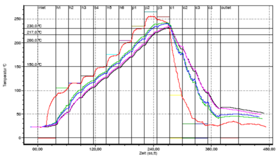
The setting of the reflow curve is also closely related to the characteristics of the PCB board to be soldered. The thickness of the board, the size of the components, and the presence or absence of large heat absorbing components around the components, such as metal shielding materials and large-area ground wire pads, all have an impact on the temperature changes of the board. Therefore, it is meaningless to generalize the quality of a reflux curve. A reflux curve must be measured for a specific product or category. Therefore, it is very important to accurately measure the reflow curve to reflect the real reflow soldering process. There are three commonly used methods for measuring reflow soldering curves:

1) Using the long thermocouple wire equipped with the reflux furnace itself (the commonly used industrial standard is K-type thermocouple wire), one end of the thermocouple wire is soldered to the PCB board, and the other end is inserted into the preset thermocouple socket of the equipment. Put the board into the furnace, and when the board comes out from the other end of the furnace, use a thermocouple wire to pull the board back from the outlet end. At the same time of measurement, the temperature curve can be displayed on the device's display. Generally, reflux furnaces are equipped with multiple K-type thermocouple sockets, so multiple thermocouple wires can be connected and temperature curves of several points on the PCB board can be measured simultaneously.
2) Use a small temperature tracking recorder. It can follow the tested PCB board into the reflow furnace. The recorder also has multiple thermocouple sockets, allowing for the connection of multiple thermocouple wires. The temperature data stored in the recorder can only be inputted to the computer for analysis or output from the printer after being fired.
3) Temperature tracking recorder with wireless data transmission. Same as the second method, except for an additional wireless transmission function. When it measures temperature inside the furnace, it stores temperature data and wirelessly transmits it to an external receiver, which is connected to the computer.
The three methods are essentially the same, and users can choose which method to use based on their habits. There are generally two types of installation for thermocouple wires, one is high-temperature soldering wire, with a temperature above 300 ℃ (higher than the highest reflux temperature). Another method is to use glue or high-temperature tape to stick it on. This way, the thermocouple wire will not fall off in the reflux zone. The position of the solder joint is generally the contact point between the solder foot of the selected component and the solder pad. The solder joint should not be too large, and it should be welded firmly. The solder joints are large and the temperature response is delayed, which cannot accurately reflect the temperature changes, especially for QFP and other fine pitch solder legs.
For special devices such as BGA, it is necessary to drill holes under the PCB board and thread thermocouple wires under the BGA. Figure 12 illustrates the thermocouple welding method for QFP and BGA components. The installation position of thermocouple wires is generally selected based on the process characteristics of the PCB board. For example, thermocouple wires should be installed on both sides of the board for double-sided boards, large IC chip pins should be installed, BGA components should be installed, and some components that are prone to cold welding (such as those around metal shielding covers and heat sinks) must be placed. Also, there are components that you believe have welding issues that need to be studied.

