How to test the reflow soldering temperature curve
Release time:2024-01-25Publisher:Jeenoce
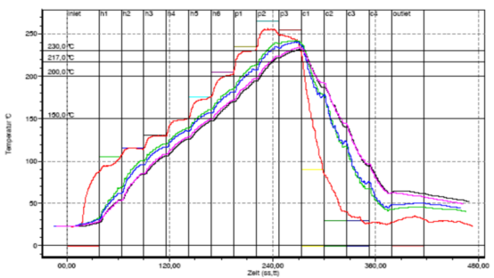
When measuring the temperature curve of reflow soldering, a temperature curve tester is required, which consists of a thermometer and a micro thermocouple probe. When measuring, K-type thermocouples (made of different materials according to the measurement temperature range and accuracy) should be used. The diameter of the thermocouple wire should be 0.1-0.3mm. After testing, the data from the memory device should be input into the PC special testing software for curve data analysis and processing, and the PCB component temperature curve should be printed.
1. The selection of testing points is generally at least three, which can represent the temperature changes on the PCB component (reflecting the temperature changes in high, medium, and low temperature parts of the PCB component); In general, the high temperature area is located at the center of the edge of the component perpendicular to the transmission direction of the PCB, while the low temperature area is located at the large component Haneda terminal near the center of the PCB (PLCC, QFP, etc.). In addition, there should be testing points on the surface of parts with poor heat resistance and specific customer requirements.
2. Installation of thermocouples: a. For thermocouples used for temperature sensing, during use and installation, it should be ensured that there is no short circuit phenomenon except for the test points, otherwise the test accuracy cannot be guaranteed. The test points should be as small as possible. b. When connecting thermocouples to memory devices or other testing equipment, their properties should be consistent with the equipment requirements. Thermocouples convert temperature into electromotive force, so there are directional requirements when connecting. (Currently, the thermocouple plugs we use have a positive and negative distinction)
3. The installation of thermocouples at the testing point should be reliably connected to the testing position, otherwise there will be thermal resistance. In addition, the materials in contact with thermocouples and the materials used to fix thermocouples should be small, as their thermal or endothermic effects will directly affect the authenticity of thermocouple measurement values.

4. Production of reflow soldering temperature measurement plate
4.1 Using a sample plate with the same production part number as the temperature measurement plate, when making the temperature measurement plate, necessary representative temperature measurement components should be retained in principle to ensure that the test measurement temperature is consistent with the actual production temperature.
If the temperature measurement plate and production part number cannot be consistent, after verification and approval by the engineer, the same type of temperature measurement plate can be used for measurement.
4.3 Temperature measurement points should be selected from representative areas and components, such as larger and smaller heat absorbing components, with priority given to component selection (such as Socket ->Motor ->Large BGA ->Small BGA ->QFP or SOP ->Standard Chip). In addition, a temperature measurement area between the two should also be selected.
4.4 Generally, there should be no less than 3 temperature measurement points on each board, and at least 4 points should be selected for BGA or large ICs, based on special representative components.
4.5 Location distribution: Adopting a full board diagonal or 4-corner-1 center point method, it can cover the distribution of the entire board position
4.6 The temperature measurement line should be fixed on the temperature measurement board with high-temperature resistant yellow tape or red adhesive.
5. Test furnace temperature curve 5.1 Based on the temperature process limits set by the engineer, the furnace temperature testing technician pre sets the furnace temperatures for each zone based on different reflux furnace structures to meet the temperature process requirements
5.2 Insert the thermocouples on the temperature measurement board into the socket of the tester in sequence. Wear a protective cover, and be sure to insert the air line into the first socket.
After setting the furnace temperature, the temperature measurement board can only be used for testing after the green light of the reflux furnace lights up normally.
5.4 Carefully place the temperature measuring plate and tester onto the reflow soldering conveyor belt or chain, and turn on the power and data recording switch of the tester. The feeding method should be the same as the produced board.
After the 5.5 test is completed, remove the tester from the output end.
5.6 Read the temperature curve on the computer and check if the curve is within a reasonable process range. Otherwise, the technician needs to continue adjusting the temperature of each zone until a temperature curve that meets the process boundary is measured.

