Side head technology for shallow gear measurement centers?
Release time:2023-10-19Publisher:Jeenoce
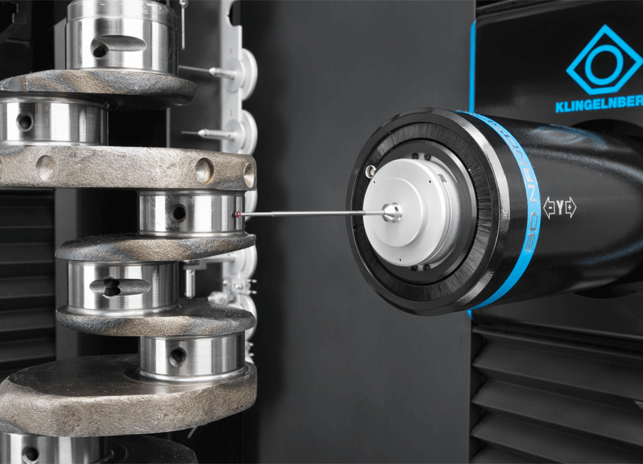
The probe technology is one of the key core technologies of the gear measurement center. This sensor can rotate 90 degrees and combine with the CNC system to add radial "trigger" function, thereby achieving "misoperation". The "two-dimensional and half" probe system formed by "protection" and overall packaging has been applied and practiced in the field of household gear measurement centers for more than ten years.
This measurement method mainly adopts the meshing rolling measurement method, which uses gears as the transmission element of rotational motion. At the theoretical installation center distance, it engages with the measuring gear to measure the overall deviation. And divide this measurement method into gear single face meshing measurement, which is used to detect gear tangential comprehensive deviation and single tooth tangential comprehensive deviation.

This technology has developed rapidly in recent years, with gears integrated into machining machines. The gear cannot be disassembled after trial cutting. Measurements on the machine must be carried out immediately, and machine parameters must be adjusted and adjusted based on the measurement results. The use of this measurement technology in form grinding and large gear grinding can effectively improve production efficiency and reduce costs.
The gear measurement center means that under the same conditions, if a parameter is measured multiple times and the measurement value is different, there are two reasons for this error: one is that the friction force of the testing machine changes during the testing process; The second reason may be due to changes in humidity in the environment where the tester is located.
The gear measurement center mainly adopts the method of geometric analysis measurement for this measurement technology. Gears are used as complex geometric entities. On the established measurement coordinate system, the geometric deviation of the gear tooth surface can be measured based on the design geometric parameters. The main methods used are discrete coordinate point measurement and continuous geometric trajectory point scanning. The error term measured through these two methods is the individual geometric deviation of the gear, mainly formed by tooth profile, tooth direction, and tooth pitch.
Using gear measurement centers as geometric entities to achieve transfer functions, or using coordinate geometry analysis methods to measure the accuracy of other individual geometric shapes, integrating the "static" gear overall error curve based on meshing order and position, or following a single side meshing comprehensive measurement method, using special measuring gears and measuring through rolling point scanning to obtain the overall error curve of gear "motion".

