Classification of heat transfer in reflow soldering
Release time:2024-05-11Publisher:Jeenoce
Reflow soldering technology is not unfamiliar in the field of electronic manufacturing. The components on various boards used in our computers are soldered to the circuit board through this process. There is a heating circuit inside this device that heats air or nitrogen to a sufficiently high temperature and blows it towards the circuit board where the components have already been attached, allowing the solder on both sides of the components to melt and bond with the motherboard. The advantage of this process is that the temperature is easy to control, oxidation can be avoided during the welding process, and manufacturing costs are also easier to control. Since the beginning of reflow soldering, the heat transfer methods of reflow soldering have also developed several generations. Currently, there are several heat transfer methods for reflow soldering, and JEENOCE will share them.
Infrared (IR) reflow soldering furnace: This type of reflow soldering furnace is also mostly conveyor belt type, but the conveyor belt only serves as a support and conveying substrate. Its heating method mainly relies on the infrared heat source to heat in a radiation manner. The temperature inside the furnace is more uniform than the previous method, with larger mesh holes, suitable for reflow soldering heating of double-sided assembled substrates. This type of reflow soldering furnace can be said to be the basic type of reflow soldering furnace. Many are used in and the price is relatively cheap.
Hot plate conduction reflow soldering: This type of reflow soldering furnace relies on a heat source under a conveyor belt or push plate to heat the components on the substrate through thermal conduction. It is used for single-sided assembly of thick film circuits using ceramic (Al2O3) substrates. Only when the ceramic substrate is attached to the conveyor belt can sufficient heat be obtained. Its structure is simple and the price is cheap.

Gas phase reflow soldering: Gas phase reflow soldering, also known as vapor phase soldering (VPS) or condensation soldering. Heating carbon fluoride (using FC-70 fluorochlore solvent in the early days) with a melting point of about 215 ℃, boiling produces saturated vapor. There are condenser tubes above and on both sides of the furnace, which restrict the vapor in the furnace. When encountering low temperature PCB components to be soldered, the latent heat of vaporization is released, allowing the solder paste to melt and then solder the components and pads. Initially used for the welding of thick film integrated circuits (ICs), the release of gas vapor latent heat was not sensitive to the physical structure and geometric shape of SMA, allowing the components to be uniformly heated to the welding temperature. The welding temperature remained constant, and temperature control measures were needed to meet the welding needs at different temperatures. The gas phase of VPS is saturated vapor with low oxygen content and high heat conversion rate, but the solvent cost is high and it is a typical ozone layer depleting substance. Therefore, its application is greatly limited, and the international community basically no longer uses this environmentally harmful method.
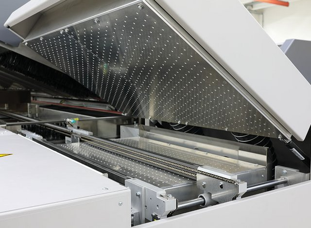
Hot air reflow soldering: The hot air reflow soldering furnace transfers heat energy through the laminar movement of hot air. By using a heater and fan, the air inside the furnace continuously heats up and circulates, and the welded parts are heated by the hot gas in the furnace, thus achieving welding. The hot air reflow soldering furnace has the characteristics of uniform heating and stable temperature. The temperature difference between the upper and lower parts of the PCB, as well as the temperature gradient along the furnace length direction, are not easily controlled and are generally not used alone. Since the 1990s, with the continuous expansion of SMT applications and the advancement of miniaturization of components, equipment development and manufacturers have improved the distribution of heaters and the circulation direction of air, and added 8 or 10 temperature zones to enable precise control of temperature distribution in various parts of the furnace, making it more convenient for ideal adjustment of temperature curves. The reflow soldering furnace with full hot air forced convection has been continuously improved and perfected, becoming the mainstream equipment for SMT welding.
Infrared+hot air reflow soldering: In the mid-1990s, there was a trend in Japan towards infrared+hot air heating for reflow soldering. It uses 30% infrared radiation and 70% hot air as the heat carrier for heating. The infrared hot air reflow soldering furnace effectively combines the advantages of infrared reflow soldering and forced convection hot air reflow soldering, and is an ideal heating method in the 21st century. It fully utilizes the strong penetration of infrared radiation, with high thermal efficiency and power saving. At the same time, it effectively overcomes the temperature difference and shielding effect of infrared reflow soldering, compensating for the impact of hot air reflow soldering on gas flow rate requirements that are too fast.
This type of reflow soldering furnace is based on the IR furnace, and hot air is added to make the temperature inside the furnace more uniform. The heat absorbed by different materials and colors is different, that is, the Q value is different, resulting in different temperature rise AT. For example, the packaging of SMDs such as lC is black phenolic or epoxy, while the lead wire is white metal. When heated alone, the temperature of the lead wire is lower than its black SMD body. Adding hot air can make the temperature more uniform, and overcoming differences in heat absorption and poor shading, infrared+hot air reflow soldering furnaces have been widely used in the world.

